Creating An Oscilloscope PC
last updated 2020-11-22 21:10:34 by Simon Vandevelde
In 2018 I got a nice oscilloscope from a friend.
It wasn't in working condition anymore, and I figured I could empty it out and turn it into a cool PC case.
That's exactly what I'm trying to do now!
 This is the oscilloscope in the state I got it.
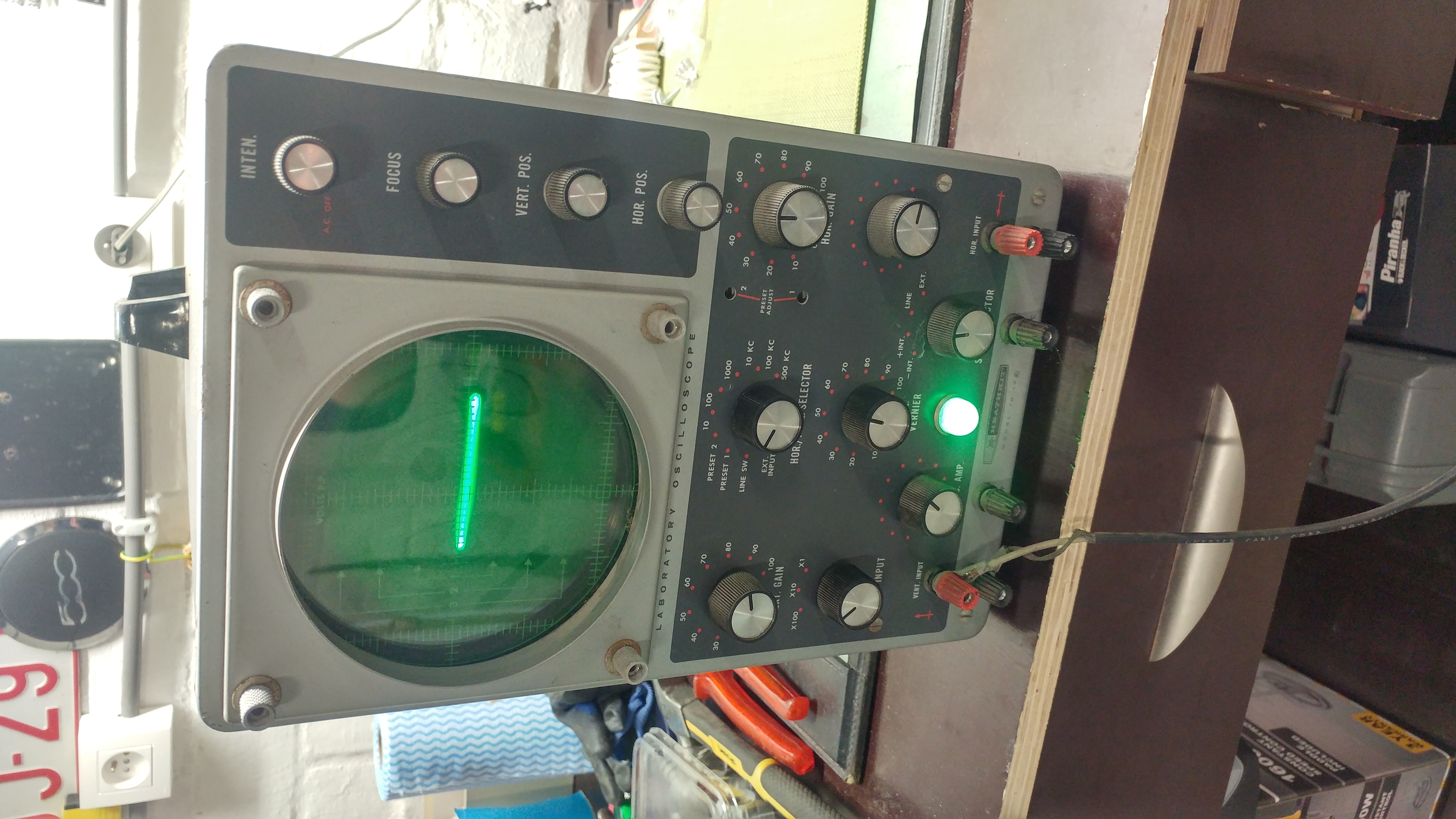 It didn't work anymore.
Besides the screen and a single LED lighting up, nothing would work.
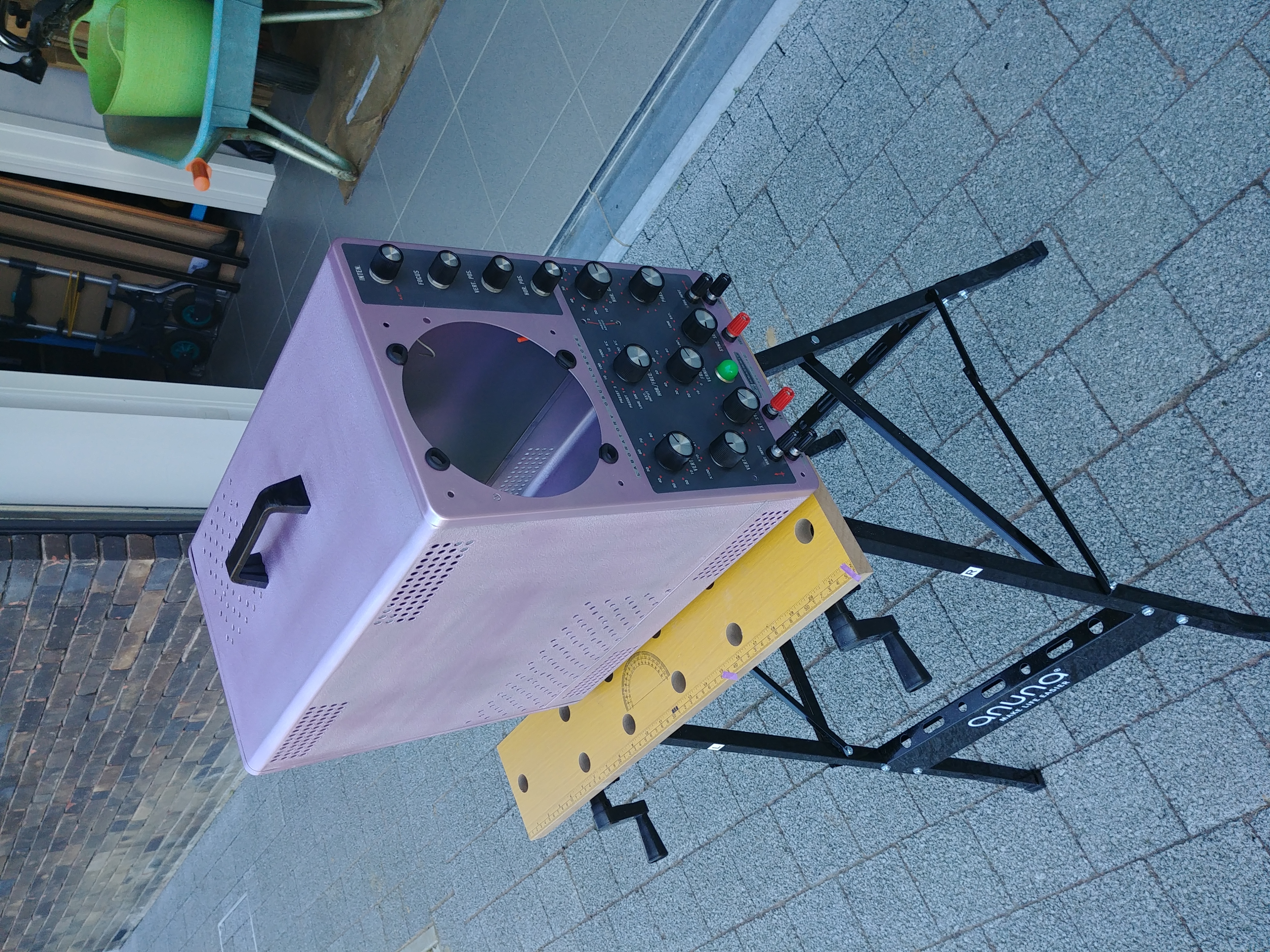
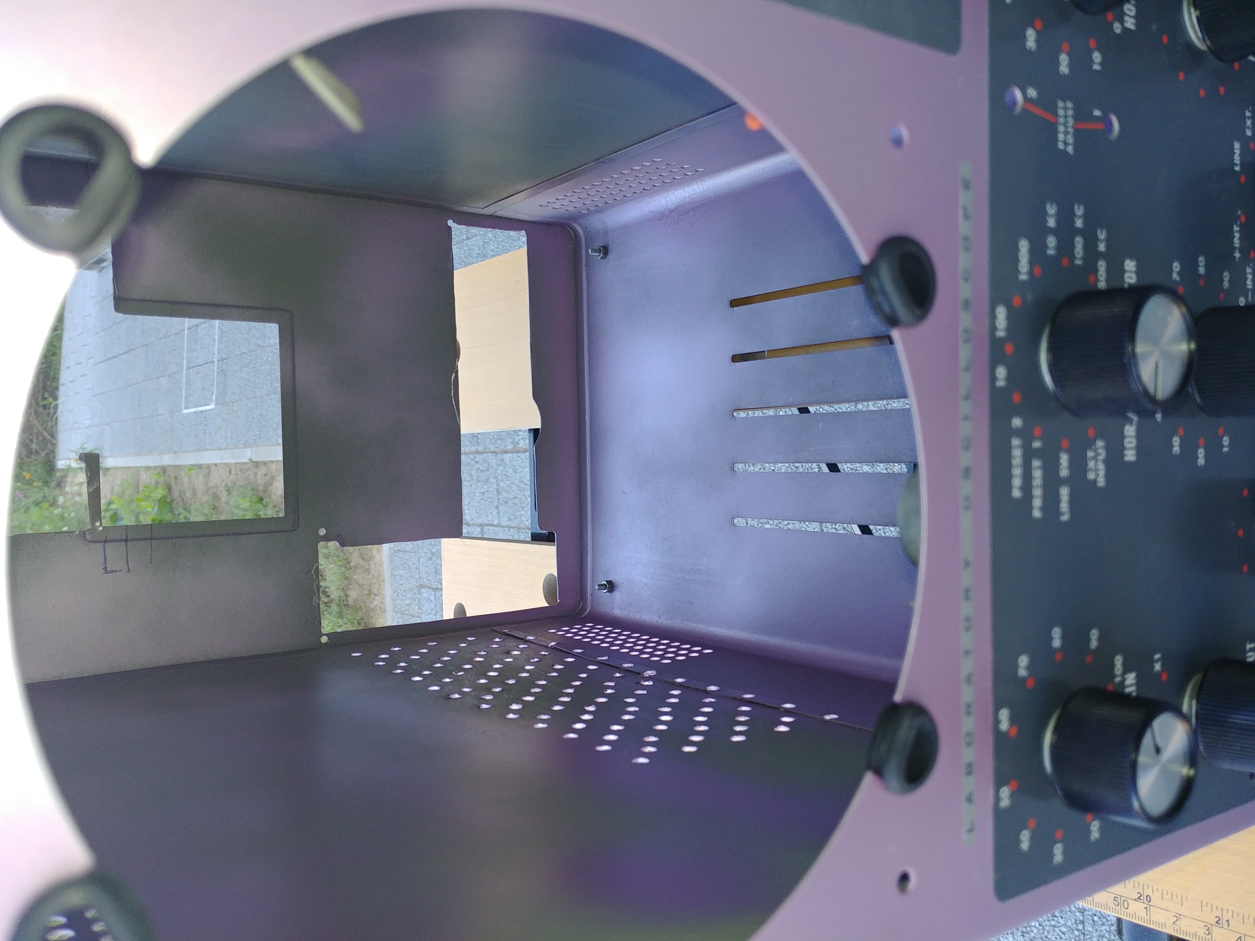
In the following step, I emptied out the oscilloscope (being careful not to break the cathode-ray tube!).
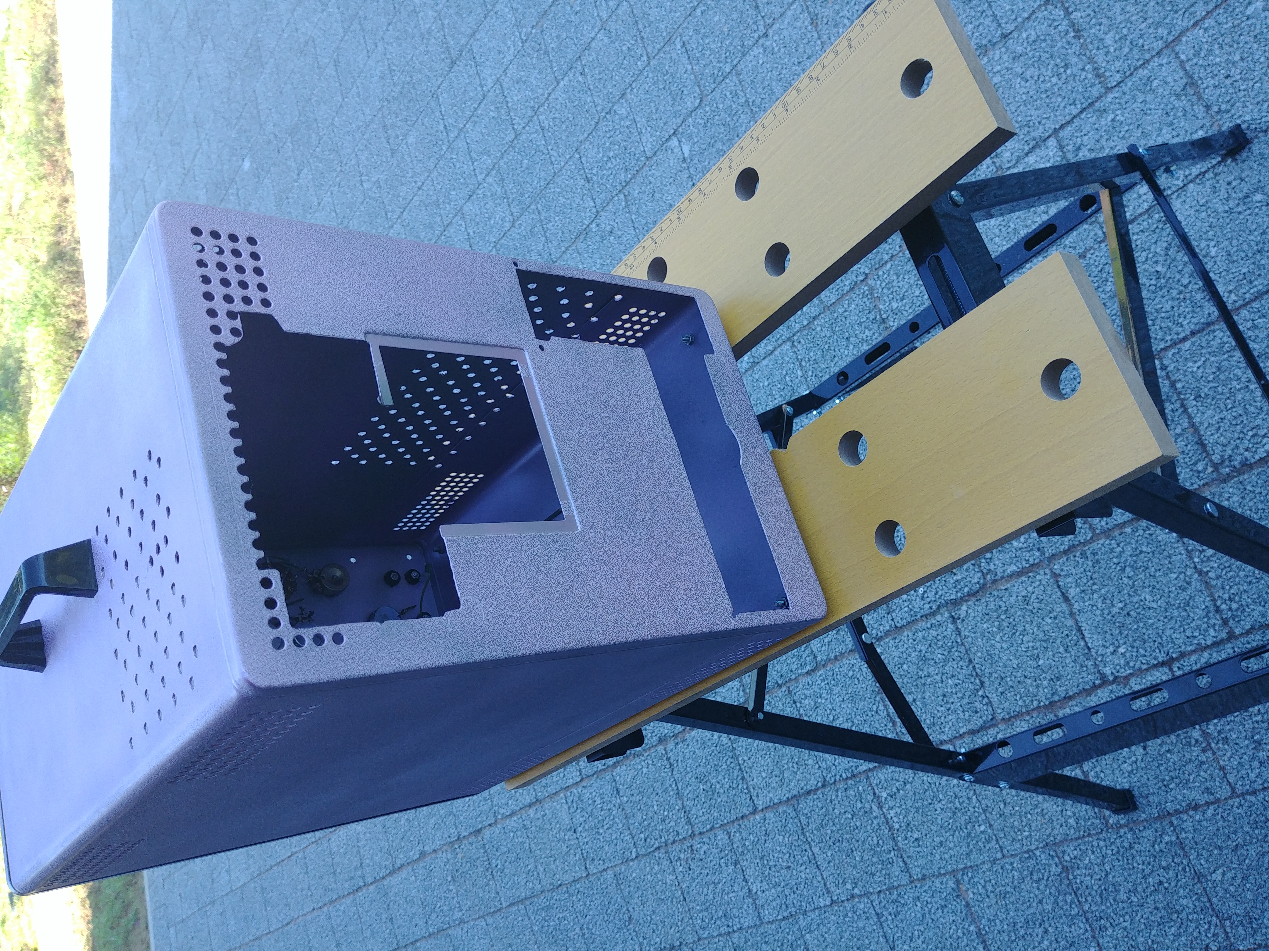
After removing all the rust, I sanded it down and cut open more openings in the case.
Both the mobo, gpu and psu needed I/O or ventilation holes.
After making these, I gave the case a nice lick of paint.
I chose for pink-purple, cause I felt like it at the time, and I haven't regretted it since.
 Now that I had a useable hull, I still needed to build a pc inside.
I felt like drilling holes for standoffs for the motherboard in the side of the case would be too permanent, so I wanted a way to easily move the pc parts in and out.
For this, I built a wooden frame which holds all pc parts.
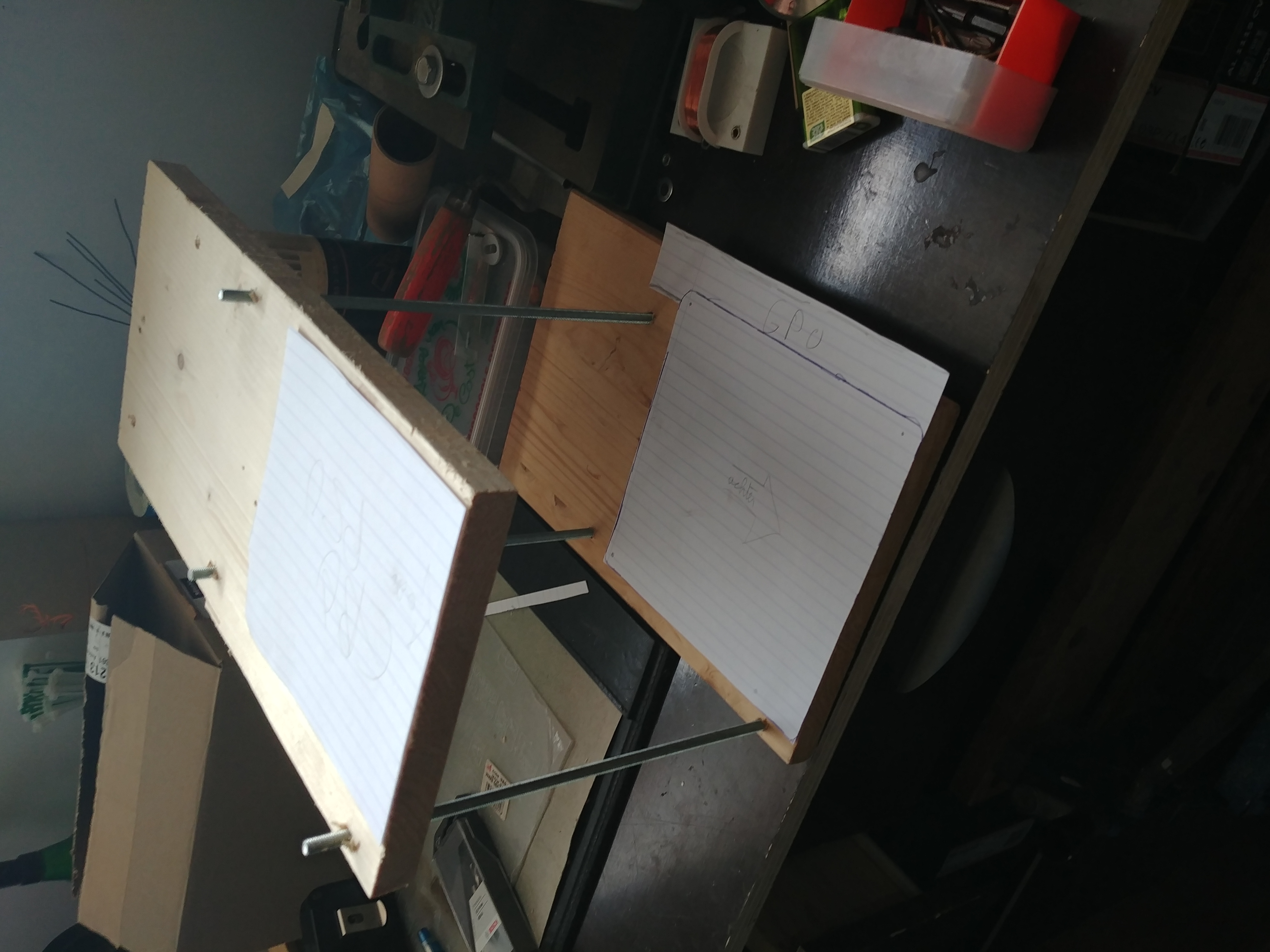 It's not the best wood, but it works.
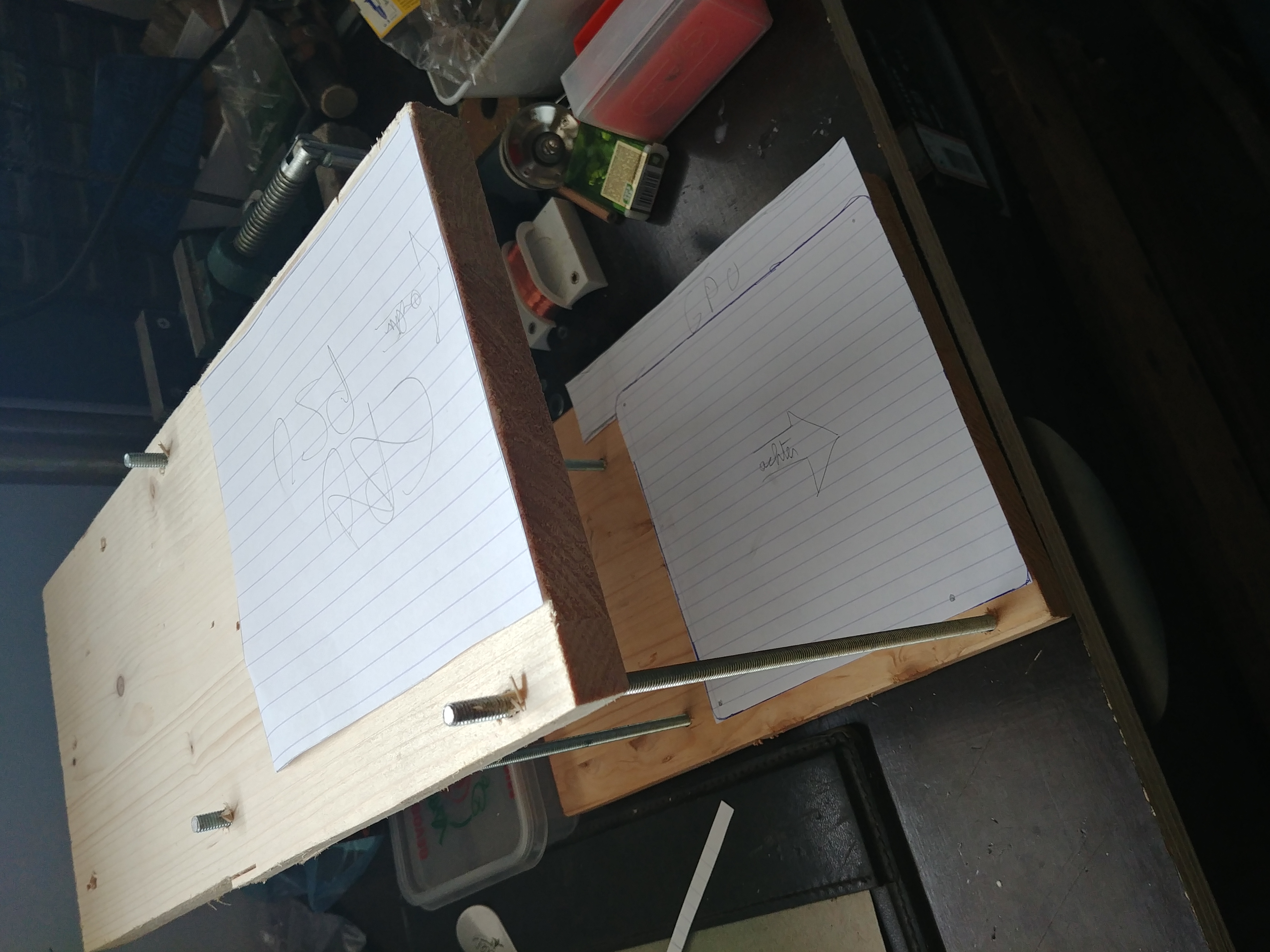 I used paper cutouts of the parts to make sure it all fits on the skeleton.
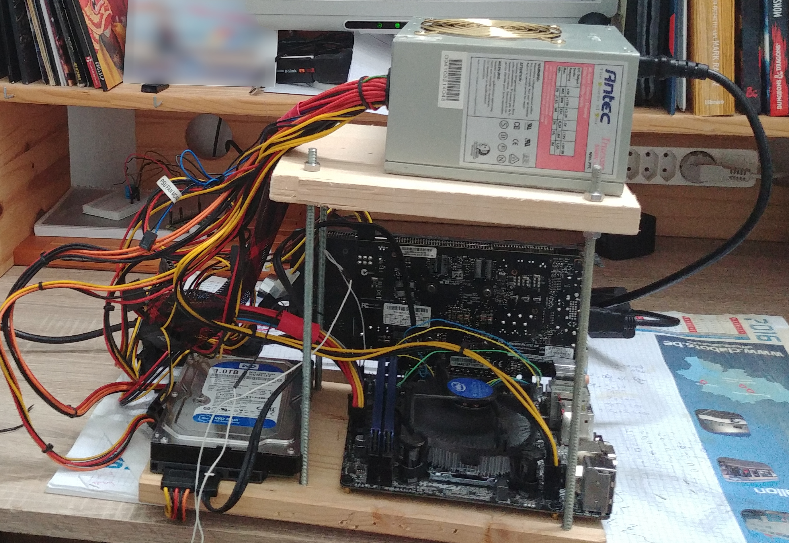 The entire pc constructed on the frame. It works!
After sliding the frame with the pc parts in the case, we have a fully working oscilloscope pc case!
However, I still have some plans for some cool visualisations and whatnot using the case.
Stay tuned for more.
Update 25/07/20 I wanted to post some more images of the oscilloscope. The above image shows the components inside of the case. I have yet to do cable management. :-)
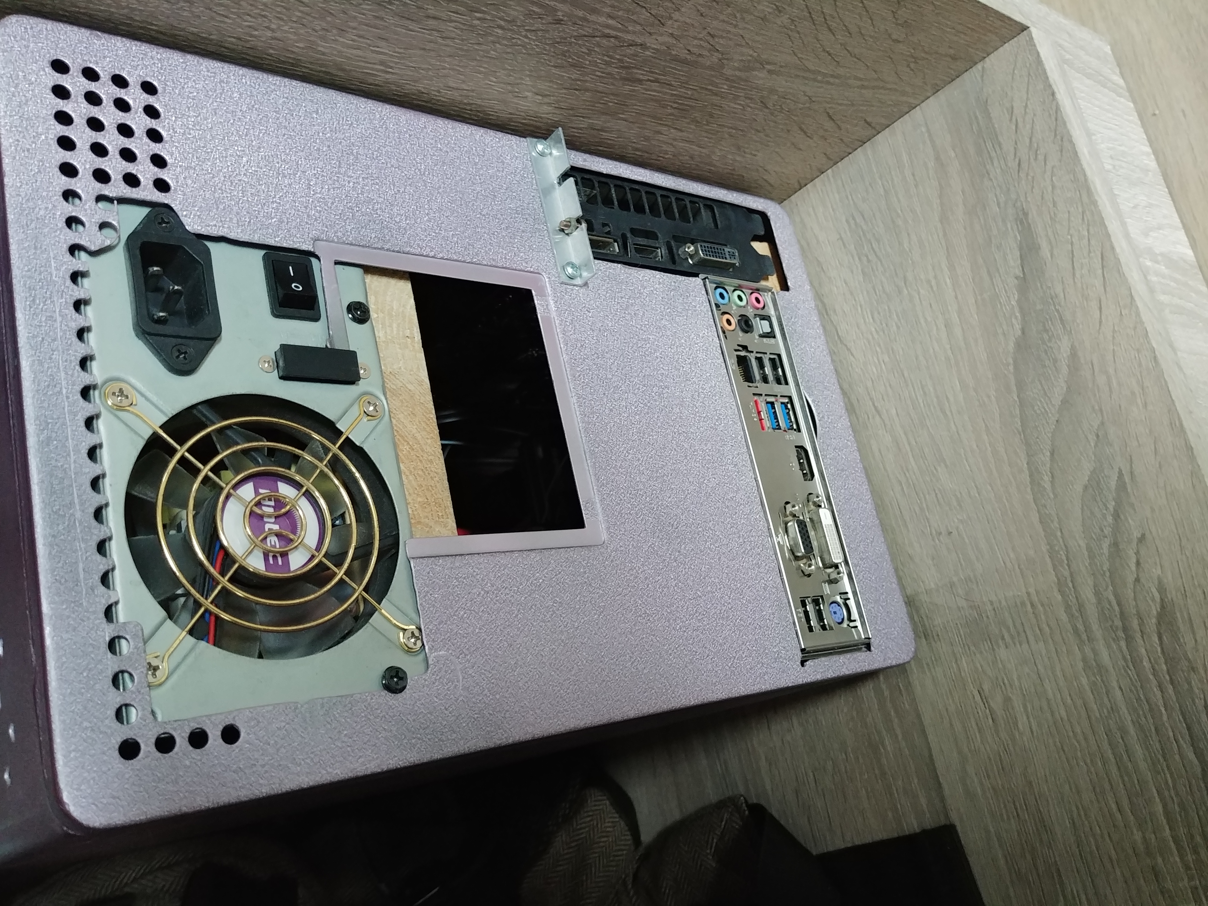
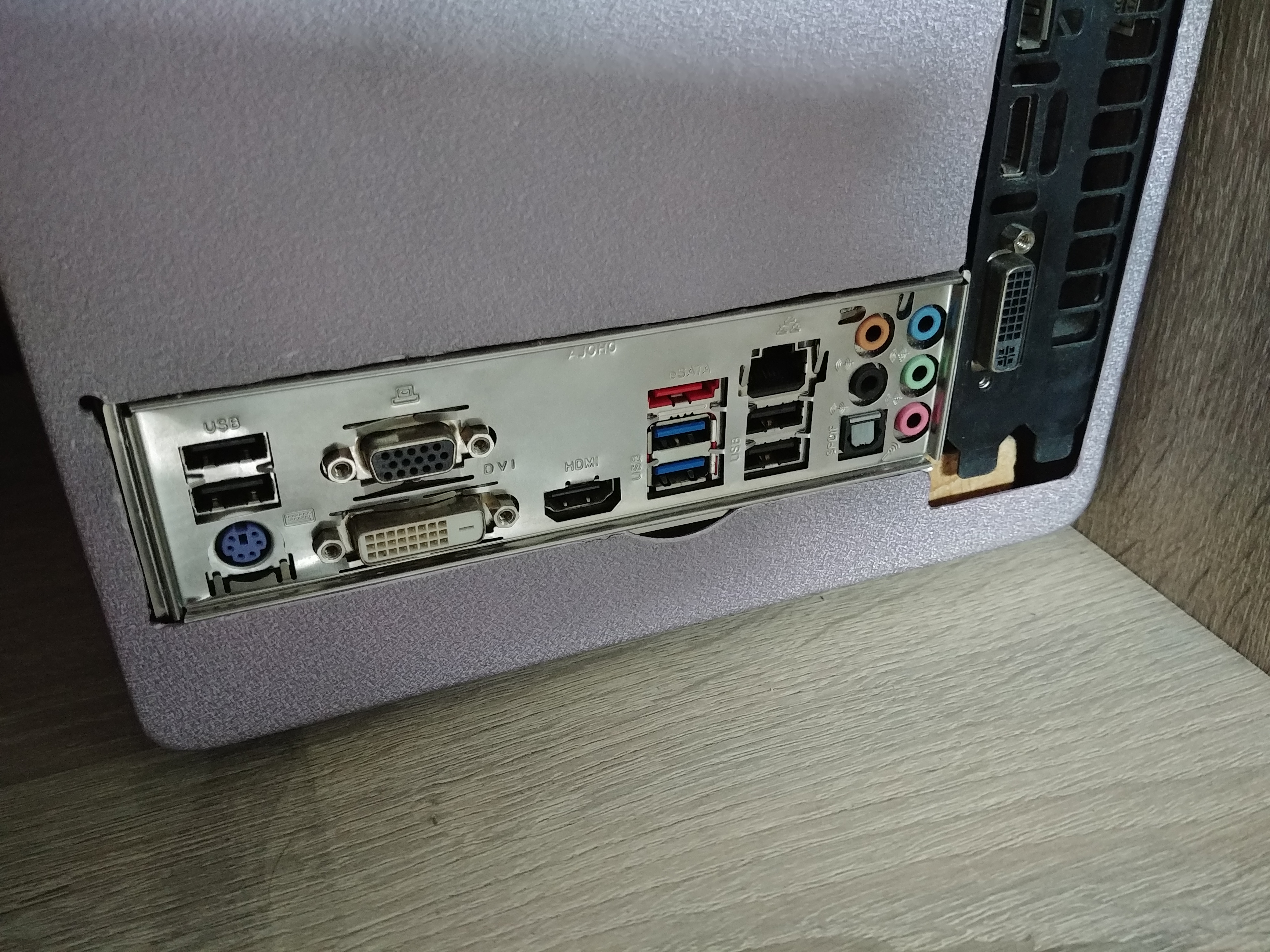 Here you can see how the components fit in the holes which I dremeled out of the backside.
The giant hole below the PSU was already there. I will cover it up in the future with a thin piece of metal.
The next step would be to add in a Raspberry Pi or an Arduino together with a small monitor where the original screen used to be.
I would like to use this monitor to display a frequency analyzer of the music which I am playing.
Stay tuned.
 This is the oscilloscope in the state I got it.
 It didn't work anymore.
Besides the screen and a single LED lighting up, nothing would work.
In the following step, I emptied out the oscilloscope (being careful not to break the cathode-ray tube!).
After removing all the rust, I sanded it down and cut open more openings in the case.
Both the mobo, gpu and psu needed I/O or ventilation holes.
After making these, I gave the case a nice lick of paint.
I chose for pink-purple, cause I felt like it at the time, and I haven't regretted it since.


 Now that I had a useable hull, I still needed to build a pc inside.
I felt like drilling holes for standoffs for the motherboard in the side of the case would be too permanent, so I wanted a way to easily move the pc parts in and out.
For this, I built a wooden frame which holds all pc parts.
 It's not the best wood, but it works.
 I used paper cutouts of the parts to make sure it all fits on the skeleton.
 The entire pc constructed on the frame. It works!
After sliding the frame with the pc parts in the case, we have a fully working oscilloscope pc case!
However, I still have some plans for some cool visualisations and whatnot using the case.
Stay tuned for more.
Update 25/07/20 I wanted to post some more images of the oscilloscope.
 The above image shows the components inside of the case. I have yet to do cable management. :-)

 Here you can see how the components fit in the holes which I dremeled out of the backside.
The giant hole below the PSU was already there. I will cover it up in the future with a thin piece of metal.
The next step would be to add in a Raspberry Pi or an Arduino together with a small monitor where the original screen used to be.
I would like to use this monitor to display a frequency analyzer of the music which I am playing.
Stay tuned.